MRMS IR ball finder 3, CAN Bus, I2C, analog (mrm-ir-finder3)
Ukratko
Senzor aktivne, infracrvene lopte za RoboCup nogomet. Pokriva 360 stupnjeva. Bitno ublažava probleme povezane s detekcijom bliskog izvora IC zračenja. Uobičajeni senzori primaju odbijeno infracrveno svjetlo od bliskih objekata, uzrokujući netočno ili fluktuirajuće mjerenje. Senzor istovremeno može pronaći i udaljene izvore, do oko 10 m, ovisno o tipu izvora. Idealan je za Robocup Soccer Lightweight Soccer jer na njega previše ne utječu protivnički roboti, ljudi oko arene, golovi, zidovi ni podloga. Vrijeme integracije je manje od 3 ms pa senzor postiže više oko 350 mjerenja u sekundi. Podatke šalje nešto rjeđe da ne optereti sabirnicu.
Cijena:
28,96 €, PDV uklj
Kupi
Osobine
|
Ulazni napon.
|
3.3 V. |
|
Sučelje.
|
CAN Bus, 2 analogna izlaza (za kut i udaljenost) i I2C. |
|
Broj prijemnika.
|
18. |
|
Valna duljina.
|
Infracrveno. |
|
Dogradnja firrmwarea.
|
Moguća. Više podataka ovdje. |
|
Zaštita od obrnutog ulaznog napona.
|
Da. |
|
Status LED.
|
Da. Više detalja ovdje. |
|
Standardizarani format.
|
Ne. |
|
Plug and play.
|
Da. Više detalja ovdje. |
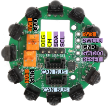
Spajanje
If You intend to get power supply from MRMS components, You will be able take a ready-made cable, like ML-R Cable KK254-KK254 10 cm (mrm-kk2.54-2.54-10).
If You do not want to use MRMS cables, standard Dupont 0.1" plugs will fit into Molex KK 254 connectors. If You want to make perfectly matching custom cables, You can buy Connector set 0xKK396 + 2xKK254 (mrm-con0-2).
You have a similar choice for CAN Bus cables: using a standard MRMS, like MRMS CAN Bus cable 10 cm (mrm-jst-can10), for connection to some other MRMS board, or to make a custom cable, to be connected to some other board. The latter choice can be implemented by using Adapter cable CAN Bus - 4 x Dupont (mrm-can-dup20). You will be able to connect MRMS CAN Bus to standard Dupont 0.1" pins.
Here are the details about 3 possible way to connect the sensor to Your system.
Softver
Želite li koristiti CAN Bus s Arduinom, posjetite ovu stranicu s instalacijskom procedurom za MRMS ESP32: Arduino, IMU, eFuse, BT, WiFi, CAN Bus (mrm-esp32). Više o CAN Bus postavkama pročitajte ovdje.
Video
Robot in action.
Reflected light
Let's take a look at the raw readings. This is a content of "cumulatives" array, a variable in sensor's ARM firmware.
In this setup there are a plenty of objects near the sensor to exaggerate the problem, but this problem exists also during the play and it consists of more than one local maximum. Bigger numbers indicate bigger probability of sensing ball in that direction.
Sensors 4 and 7 read 122 and there are some more close to that value. It is quite hard to determine the direction of the ball.
The problem is reflected light.
Nearby parts of the robot reflect light (the reception angle is rather wide) but also walls which may be far but tend to be big and bright and also other objects.
Another part of the problem is the ball as it has discrete IR light sources, LEDs. A sensor pointing towards the ball may be directed between LEDs and some other LEDs may illuminate reflected surface directly.
This problem is hard to solve perfectly. However, putting apertures in front of receivers will help.
Screen
Here are the readings after covering the top sensors and putting a black area below the sensor. Now the result looks much better and it is easier to find the direction.
The results will not be always like this and there still can be more local maximums, but the situation got better.
Construction
On the left is one idea how to construct the apertures.
Download 3D printable file:
IRFinderCover v3.stl or a file to be modified in Autodesk Fusion 360:
IRFinderCover.zip.
This is just an example, not a perfect enclosure. You may try with smaller apertures.
Alternative construction
Screen's shortcoming
Will the apertures be a perfect solution? They will not.
IR Ball has discrete IR light sources, LEDs. Let's consider the situation like in the picture.
No ray goes directly to the front sensor (2) and it is illuminated poorly.
Ray A hits obstacle A and enters side sensor 1 at 90°.
Ray B finds another obstacle and enters sensor 3 at an angle that is far from right angle.
If we construct apertures, no matter how tight they may be, we cannot solve the problem with ray A. It will illuminate sensor 1 more than indirect light illuminates sensor 2. In that case, the sensor will report the ball to be in direction of sensor 1.
Enclosure will eliminate ray B problem as it will block all the rays that do not enter sensor close to the right angle.
When ball is far, the apertures will be useful. When it is near, it is necessary to remove all the shiny objects that could reflect the light as the sensor is overwhelmed with IR light.